Drawings I have done sorted by date or something
Mk1 Heavy duty sex machine
This is my on-going project Once complete the full instruction kit with models will be available for a donation.
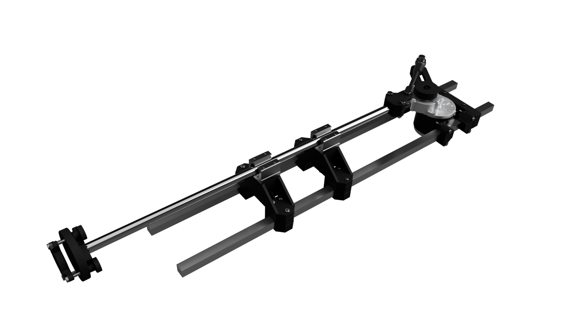
This is a high powered high speed adjustable sex machine based off cheap readily available parts. You only require a 3d printer, drill, basic drill bits and basic hand tools.
All the parts should be under $200 usd so its cost competitive to other designs while being able to deliver more speed and power. It has an adjustable stroke length from 75mm to 195mm and with modifications the stroke length can be up to 300mm. uses a high powered geared brushed dc motor and basic electronics to drive it. The power output of the motor is 250w which combined with the torque of a brushed motor will stir your guts even at max stroke with a large toy.
Unlike other CNC rail based machines this is also almost completely silent as I have opted to use round rails and plastic bushings. The linear rail sex machines suffer from noisy bearings and its always killed my interest in them. The loudest part of this machine is the gear lash in the motor.
The downsides is that you cannot adjust the stroke length while its moving and its a tad heavy.
All 3d printed parts where printed using Esuns ABS+ Filament on a prusa I3 mk3. It is a must that your printer is accurate. The models have tolerances built in assuming slight print errors, There is no tolerance for print shrinks. I would recommend printing these parts in ABS, You can print them in PLA however I would highly warn against it as the motor during high use can get hot enough to weaken it. I would also advise against using carbon fibre filaments of all types. You really don't want to get tiny CF hairs in your butthole. Just stick to ABS+ or use caution with other filaments. The base line is ABS so anything above that if you can print it will be ok.
You will need some basic tools, Grinder for modifying part of the motor, drill and basic bits for cleaning up bolt holes and a basic tool kit for tightening the bolts. This machine will require a little bit of handy work to assemble.
Part 1, Motor mount
This whole model is based off 20mm x 1.6mm box tube, You can use aluminum however the wall thickness needs to be at least 2.5mm ideally 3mm, you want to use very stiff sections. Hollow round bar will not work as the flat section is what keeps the motor steady.
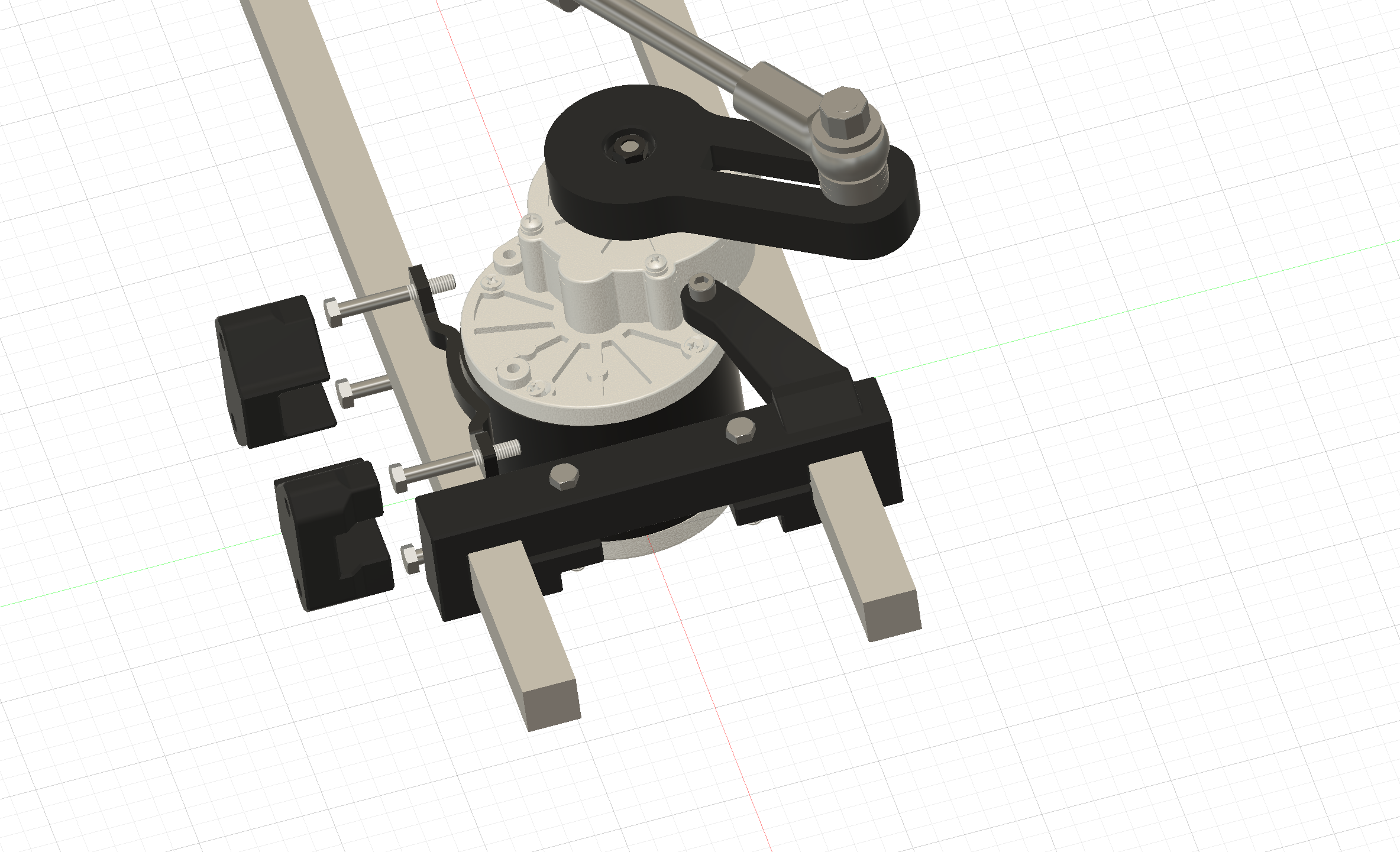
The motor mount to the left, it consists of 2, 3D printed rail holders that bolt directly to the motor feet. using 45mm M6 bolts and washers (not shown) To note in the screenshot the motor is clipping. This is due to some of these motors not being made exactly to spec and thus sit aprox 4.9mm closer to the bar tube on the left. This does not affect assemble apart from one piece...
The rear bar holder, This is a simple bracket to hold the end of the bars together and to prevent twisting of the whole machine. 2 45mm M6 bolts clamp it to the tube and a single 25mm m6 bolt/washer attached to the top as an extra support. In the model I used a cap head since its what I had on hand however a bolt and washer will work.
The extra motor attachment on that rear bar is only there for looks and to add a little more rigidity, If in testing it breaks a lot then I will redesign or omit it however its very unlikely in my current tests of it.
Part 2, Rail and bearing mounts
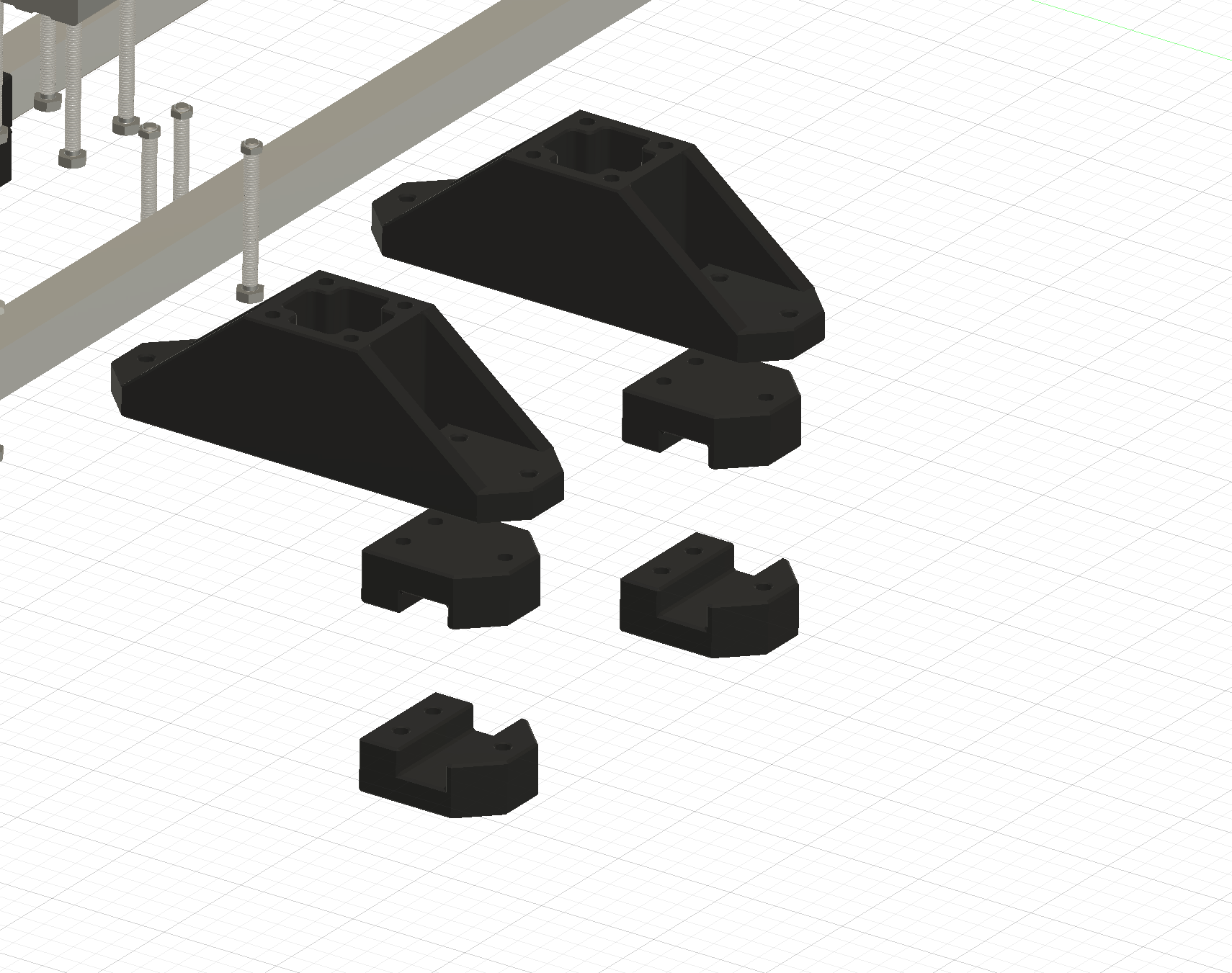
The bearing block mounts, I only had 20mm rail laying around however the released model will use ether 10mm or 12mm bearing rails as 20mm is far far too heavy and overbuilt. The bearing mount consists of 5 parts.
Part 1. The main bridge, This is where the bearing block is attached to, 4, 70mm m6 bolts/washers to secure the bearing block to the frame while also adding rigidity. This is also the main way the box tube is held in place.
Part 2, The upper cap. This is what the main bridge sits on, it acts as both a spacer and the frame work of the box tube clamp in case it needs to be slightly resized.
Part 3, The lower cap. This is where everything comes together. Using the same 70mm m6 bolt the whole assembly is clamped together using 3 bolts/nuts/washers on each side and torqued down.
The whole assemble is bolted together fairly easily. Keeping the nuts loose allows you to slide the blocks to where you want them. You want to space them about 150mm from each other and 320mm from the foot of the motor. The distance to the motor is dependant on stroke length.
The bearings have been changed to plastic bushes, Bearing are super noisy and it always irked me with other sex machines. Replacing them with bushes massively cuts down on the noise at the cost of less dynamic load handling. However for a sex machine it will be ok. When building I would have an extra set on hand just in case. Another upside is that the nylon or PTFE ones do not require lube and thus stay clean and don't track oil or grease which can ruin toys.
Part 2.5, Motor to rail connecting rod
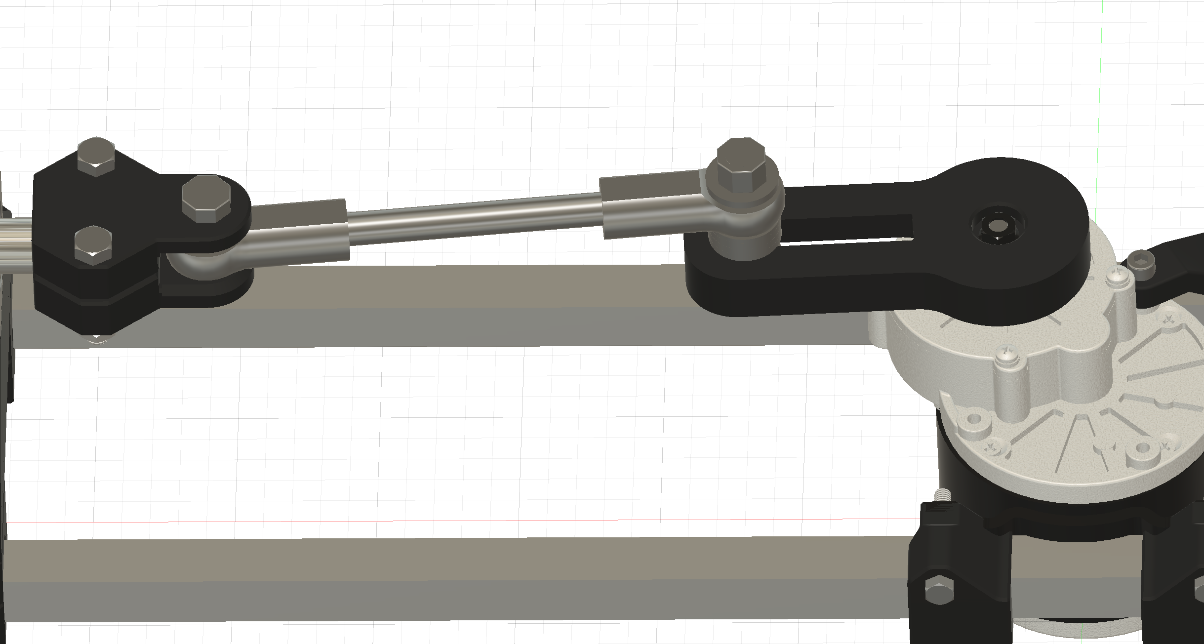
Another simple part. There are 2 rod ends with 150mm of threaded rod with locking bolts (not shown). The rail end is a simple 2 part clamp with 2 m8 50mm bolts/nuts/washers with an m12 60mm bolt/nut/washer connecting the whole shebang to the connecting rod end. This part will see a lot more dynamic forces compared to the rest of the machine so when printing make sure to increase infill to 60% and all walls/top/bottom layers to 2x.
Part 3, Crank shaft.
The crankshaft is a bit unusual in the way its fitted to the motor. The underside has an exact cutout of the sprocket that comes fitted to the motor. Depending on the variant shipped you will need to flip the sprocket on the shaft and grind the extrusion where the shaft passes though down about 2mm till its almost flat with where the teeth are, This is to allow the threaded part to pass though the plastic and so the bolt can bite into it. In the screenshot you can see the bolt clipping. This was moved after modifying my motor and gives a glimpse into what is required.
The sprocket is then pressed into the crank for a tight fit and the whole assemble is slid back over the shaft with the retaining bolt holding everything together. This system provides a very strong connection to the motor shaft without the use of custom metal parts. I did try a direct shaft fit but as you can imagine it just ripped the plastic to shreds.
The rod end of the crank uses a m12 cap bolt recessed inside a cut out, Said cutout is stepped to allow the square shank of the cap bolt to sit in so you do not require extra tools to tighten the holding bolt. The thread sticks up and the rod end attaches to that via washers. The rod ends allow for some misalignment so unlike the model you only require a single washer.
Adjustment is easy as undoing the bolt and sliding the bolt up or down the cut out. You can also modify the model and allow a much longer stroke for the real sluts out there. Right now the minimum stoke is 75mm and the max is 195mm. 75mm Might however be a little too deep for some users so I would test your own limits before building this machine.
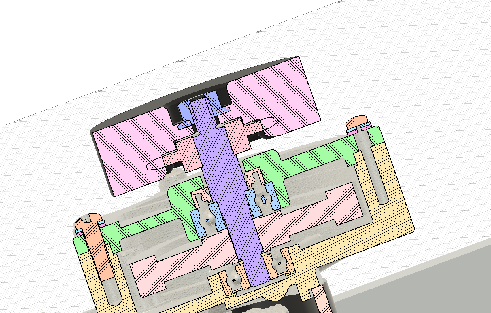
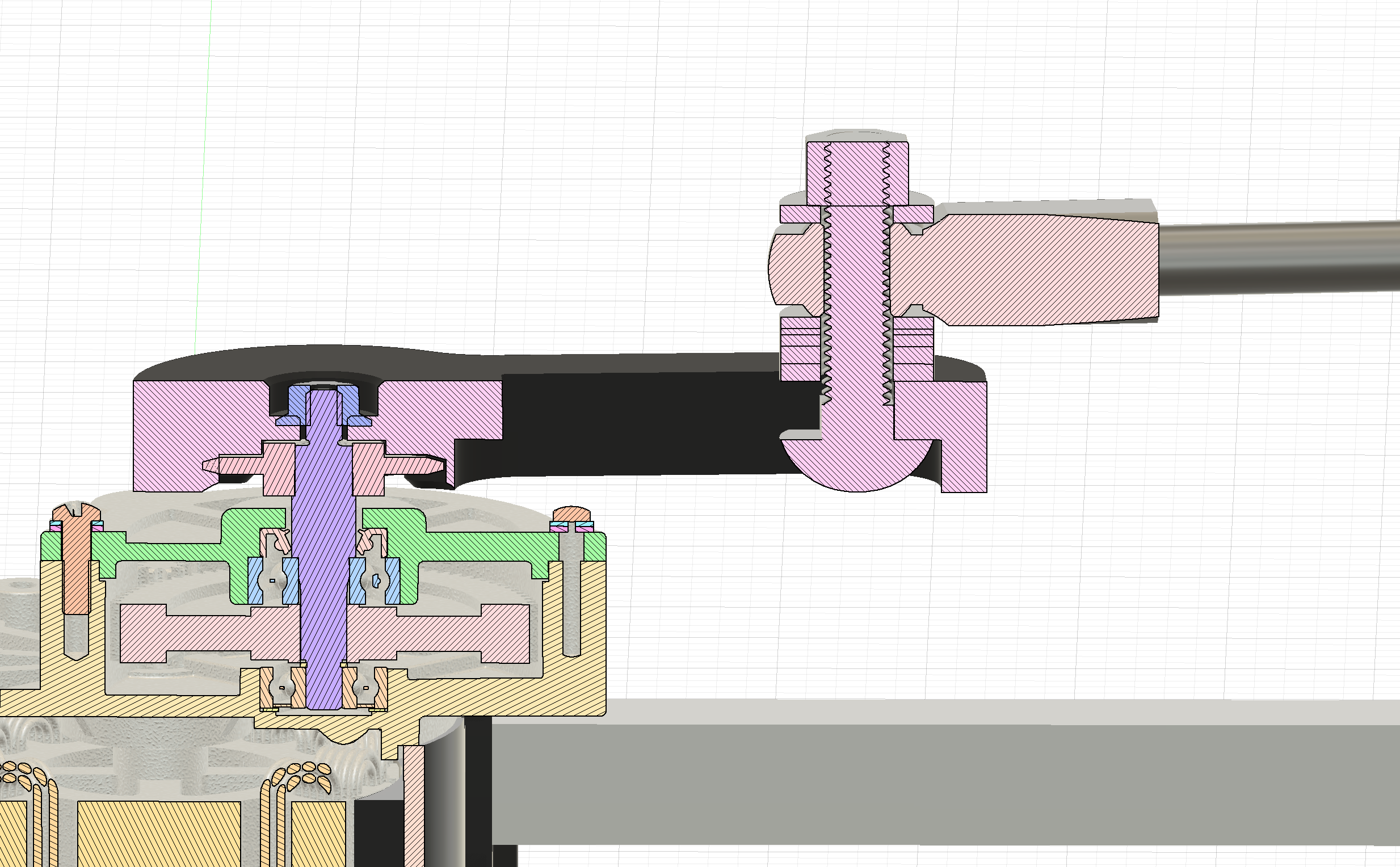
Part 4, Toy attachment.
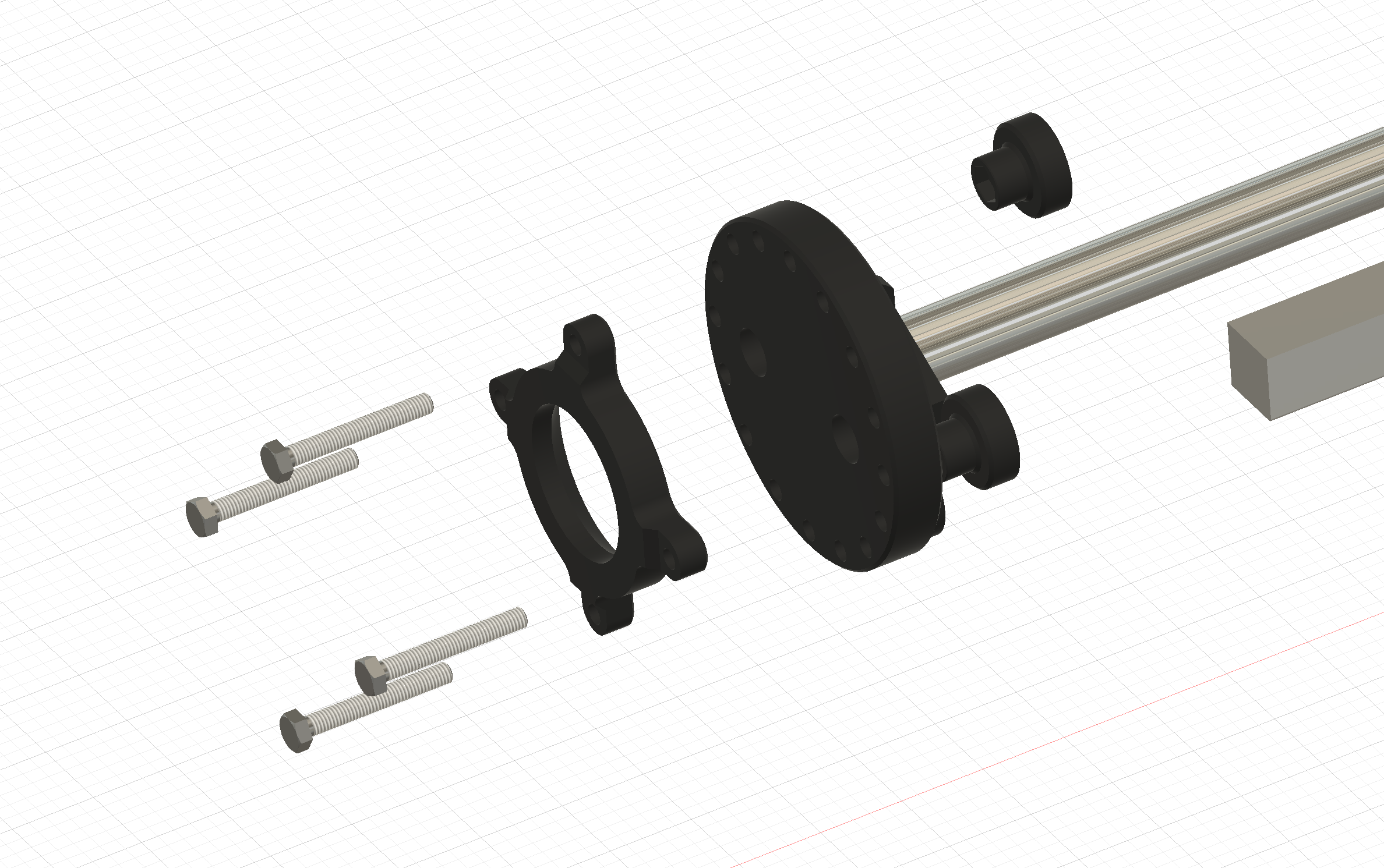
Toy attachment is simple, its just a 100mm round plate with 6.2mm holes. On the rear is a flange to mount it to a metal rail flange support. the rail goes into the middle of the round plate to help increase rigidity
The holes can be used to tie toys to the plate or in this case use a retaining ring. Multiple sizes will be provided, I only have a limited amount of toys to design retainers for so some CAD modeling by the end user will be required for more weirdly shaped toys.
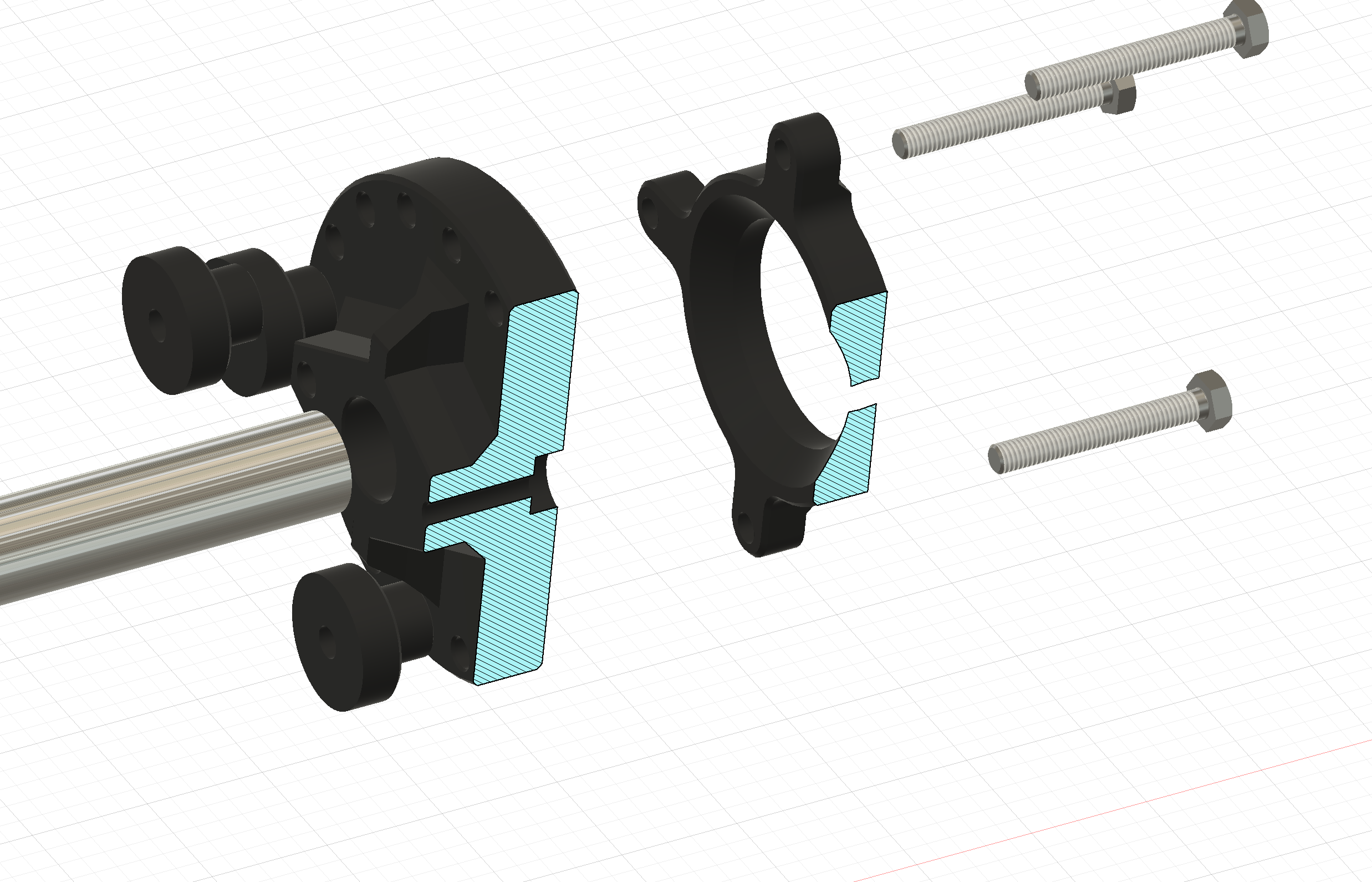
This ring is held in place using m6 45mm bolts and flange nuts that have been pressed into thumb screws. the bolts require very little torque on the nuts to clamp toys in firmly. The bolts do not require a step to stop the head from spinning. only 2 are needed but 4 helps keep the print time down.
Part 5, Electronics work in progress
Currently the electronics is just a PWM controller, 24v 300w power supply. The plan is to have a wireless remote and enclosed pwm controller mounted to the machine itself. Since arduino has been bought out by qualcomm I have decided to go with an ESP32, its a little over powered but will do the job. This will come in the future.